Wrist Worn Haptic Feedback Device

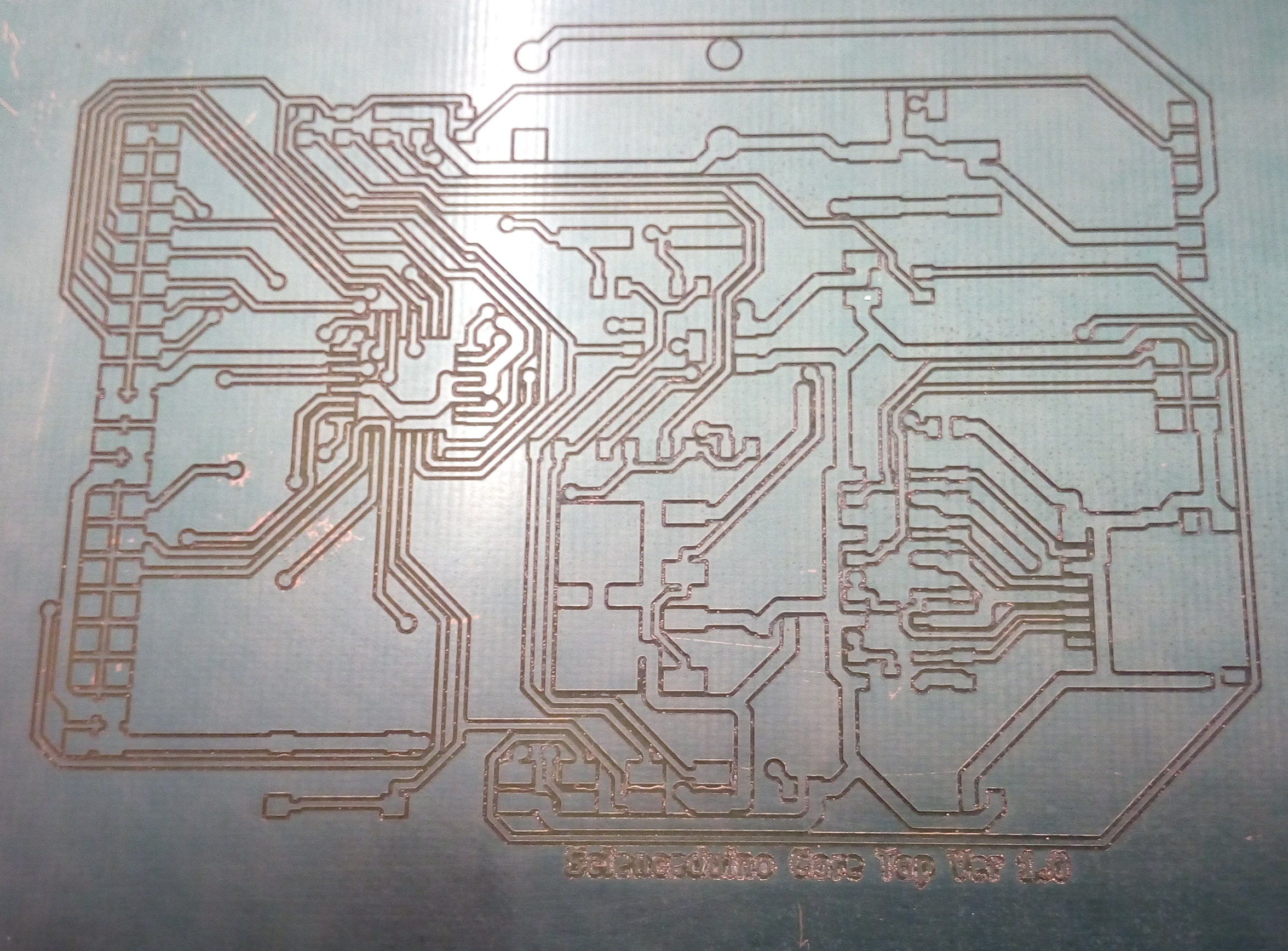
One of our PhD students Esma Mansouri Benssassi and her supervisor Dr Erica Ye defined a requirement for a wrist worn device to group a number of Haptic feedback elements for an experiment they wished to carry out. The on-board Haptic elements are two eccentric rotating mass micro motors and an linear resonant actuator. Initial circuit schematics and printed circuit board designs were created in an Open Source Electronics Design Automation Suite KiCAD EDA. The resulting printed circuit board (PCB) design was made on the CS CNC Router , this produces the PCB by engraving the copper clad fibreglass-epoxy board with a Vee cutter.

PCB
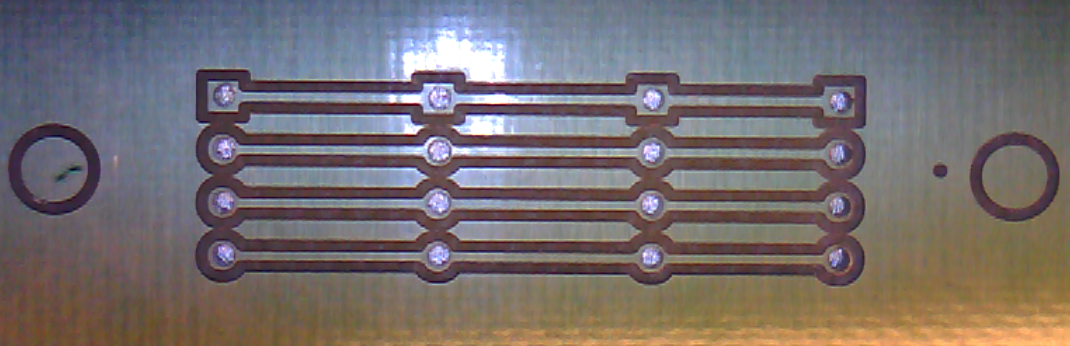
Bare Circular Engraved PCB

The case for the PCB was created in Autodesk Inventor and was 3D printed using the CS Makerbot 2X 3D printer.

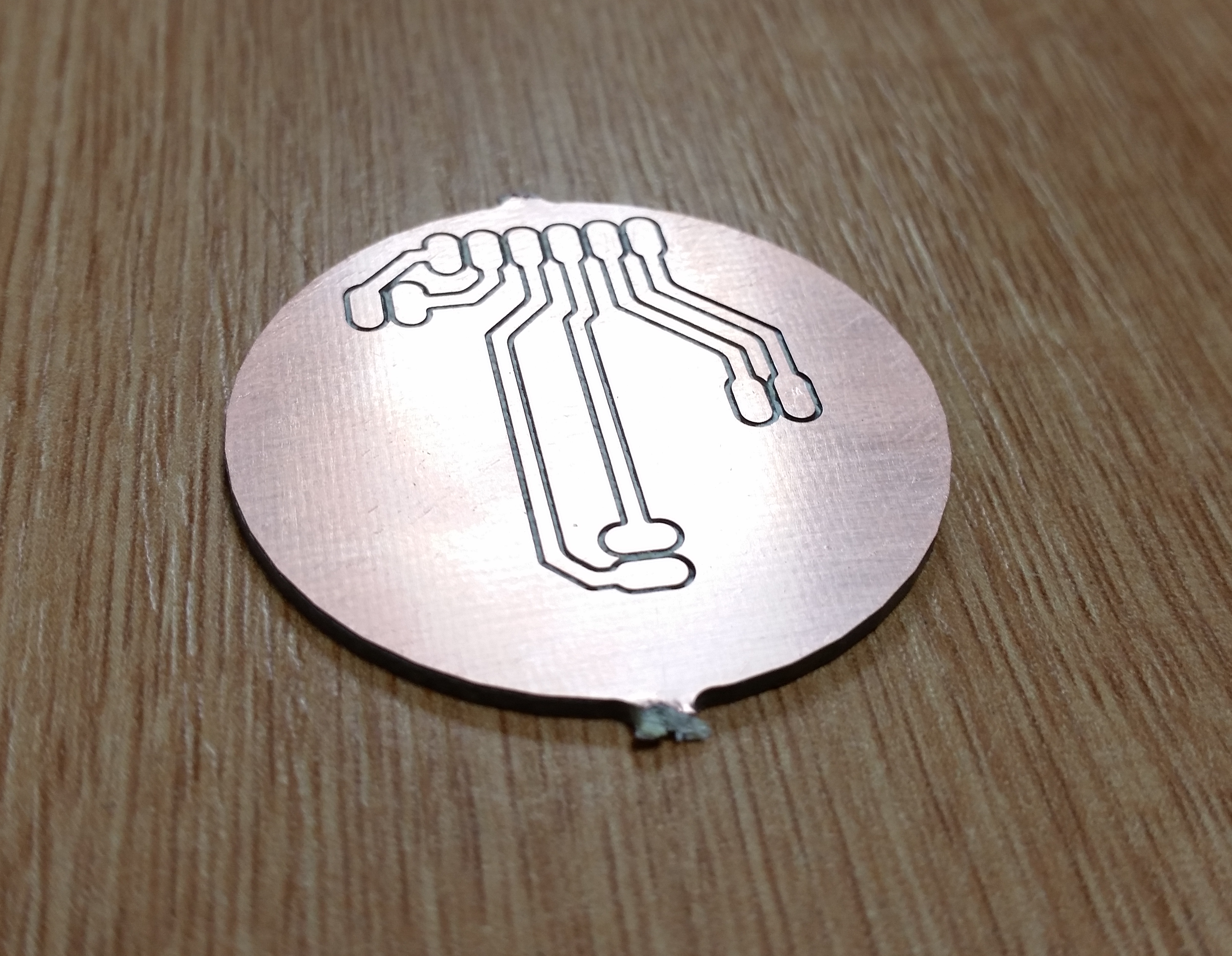
Blank PCB and 3D Printed Case

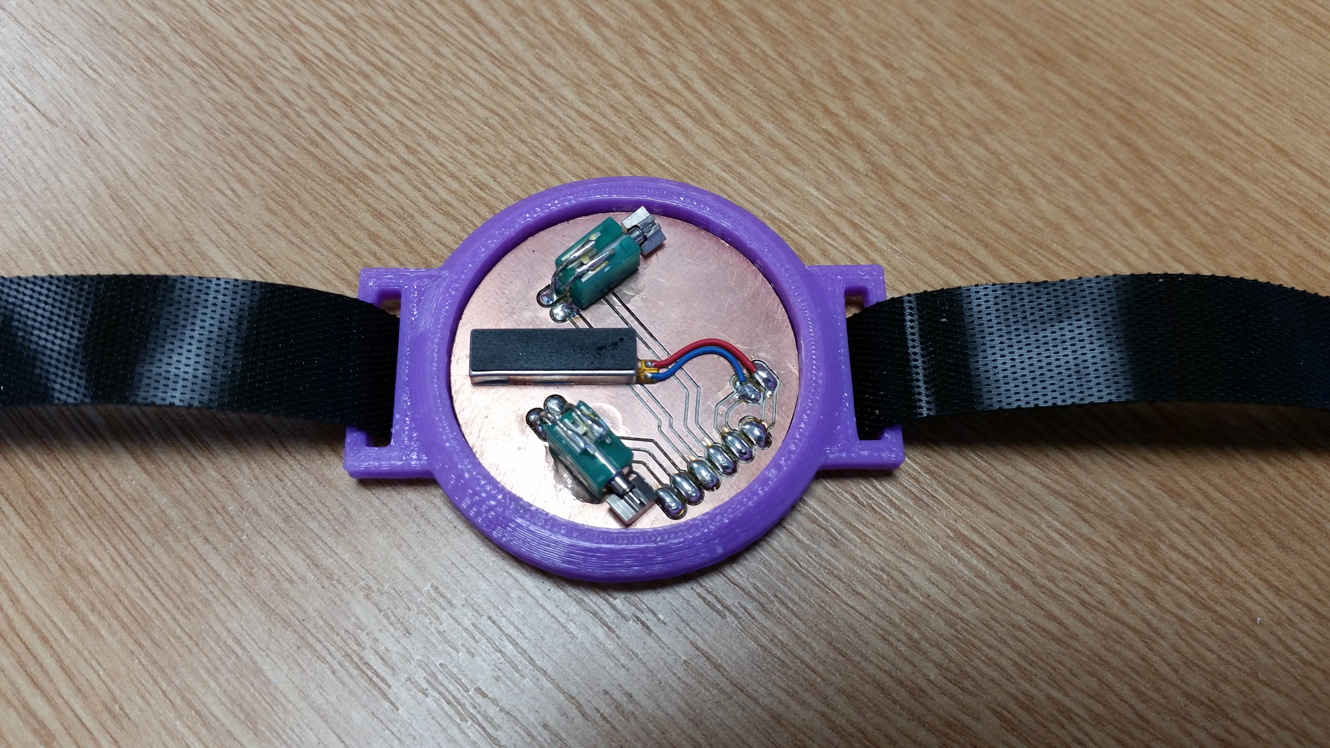
Haptic Wristband and Haptic Transducers

The wrist worn Haptic feedback device will be connected via an umbilical cable to the main control Feather M0 embedded ARM and Haptic Driver breadboard. This is an ARM microcontroller and wifi module which can be programmed using the Arduino IDE. Code for the ARM processor will enable stored and custom waveforms to be played on the haptic devices on the wrist.

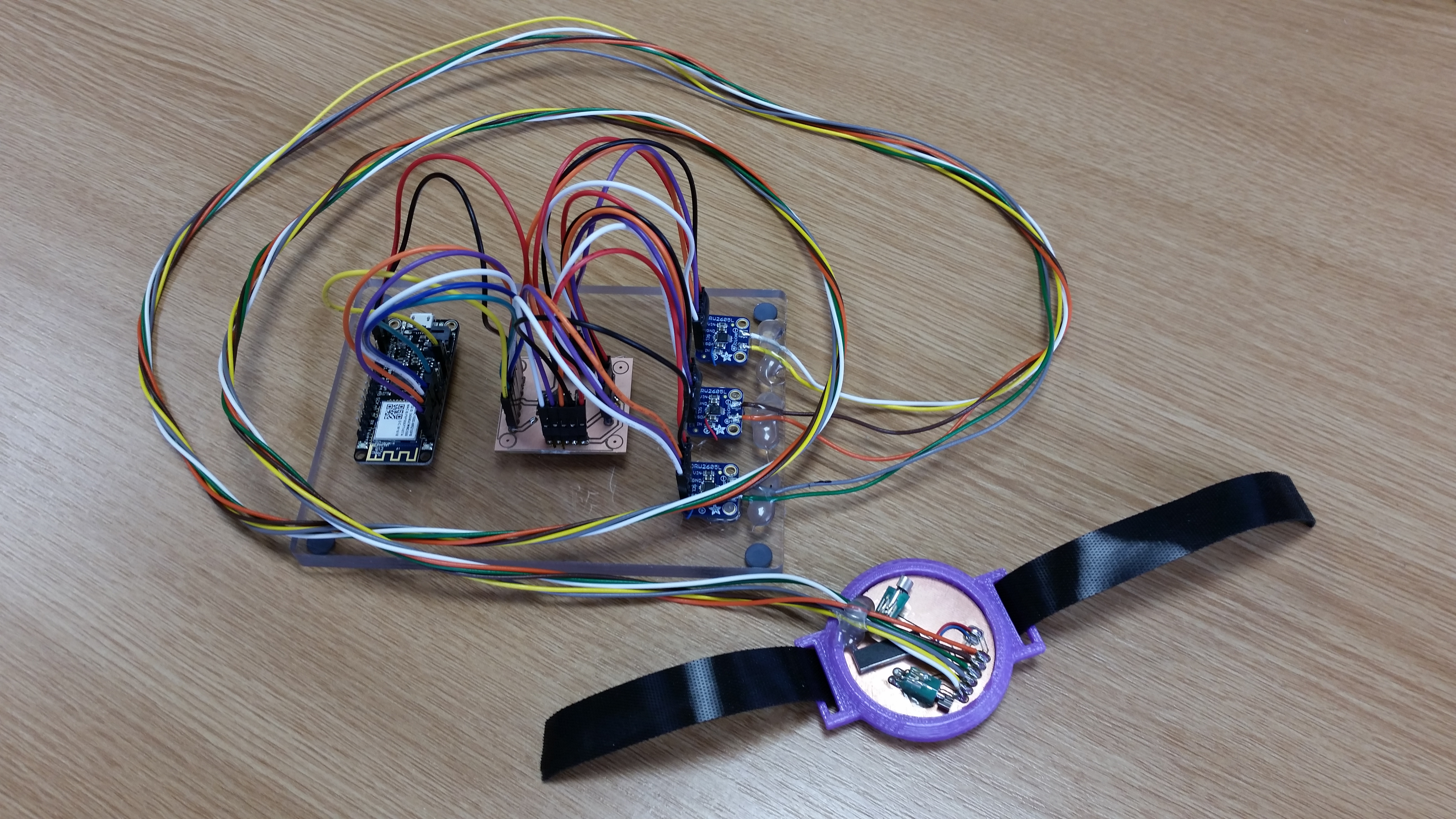
Haptic Feedback Breadboard Assembly

CNC Router Test PCB Made

The first real test of the CNC Router milling a printed circuit board took place this week and the results so far are very encouraging.

Scienceduino PCB

The PCB design is part of a suite of hardware required for a research project. This involves the development of a Science grade Arduino we have called Scienceduino , it will be used to log analogue data with a high degree of accuracy and traceability , in terms of readings and time logging. The picture of the complete PCB shows the complexity and general layout of the components , these will be mostly surface mount. Surface mount technology is being used to help reduce the overall size of the system and to allow automated manufacture.

PCB Microscope Image

The microscope webcam picture shows a circular pad which is 1.0mm in diameter , track width of 0.35mm and track spacing of 0.35mm. The copper flakes in the gaps on the PCB will be cleaned away with water and detergent. So all in all this is good news for the School’s ability to manufacture PCB’s for various research projects.

A New CNC Router

CNC6040
A new CNC Router has just been undergoing its initial testing and calibration procedures. Its purchase was jointly funded by the School and the Research Groups of Professor Al Dearle , Professor Simon Dobson and Dr Miguel Nacenta. The router will be used for the manufacture of printed circuit boards , it can also be used to machine Plastic and Aluminium parts for research and student projects using suitable 3D CAD software such as FreeCAD. All the software used thus far has been Open Source and is as follows LinuxCNC for the machine controller , KiCAD for PCB design , pcb2gcode for the conversion of the Gerber file generated by KiCAD into GCode for the CNC Router. This allows one to manufacture PCBs using the copper isolation method , this is done using the Router cutter to create individual tracks on the blank copper PCB material using the generated GCode of the PCB design.

A PCB

The image above shows a newly made PCB that has been routed and is also drilled ready for electronic components to be inserted.